To support the
increased use of natural gas in Hong Kong from 2020 onwards, Castle Peak Power Company
Limited (CAPCO) and The Hongkong Electric Co., Ltd. (HK Electric) have identified
that the development of an offshore liquefied natural gas (LNG) receiving
terminal in Hong Kong using Floating Storage and Regasification Unit (FSRU)
technology (‘the Hong Kong Offshore LNG Terminal Project’) presents a viable
additional gas supply option that will provide energy security through access to
competitive gas supplies from world markets.
The Hong Kong Offshore LNG Terminal Project will involve the
construction and operation of an offshore LNG import facility to be located in
the southern waters of Hong Kong, a double berth jetty, and subsea pipelines
that connect to the gas receiving stations (GRS) at the Black Point Power
Station (BPPS) and the Lamma Power Station (LPS).
The Environmental Impact Assessment (EIA) Report for the Hong
Kong Offshore LNG Terminal Project was submitted to the Environmental
Protection Department (EPD) of the Hong Kong Special Administrative Region
Government in May 2018. The EIA Report
(EIAO Register No. AEIAR-218/2018) was approved by EPD and the associated
Environmental Permit (EP) (EP-558/2018) was issued in October 2018. An application for Further Environmental
Permits (FEP) was made on 24 December 2019 to demarcate the works between the
different parties. The following FEPs were issued on 17 January 2020 and the EP under
EP-558/2018 was surrendered on 5 March 2020:
§ the double berth jetty at LNG Terminal under
the Hong Kong LNG Terminal Limited, joint venture between CAPCO and HK Electric
(FEP-01/558/2018);
§ the subsea gas pipeline for the BPPS and the
associated GRS in the BPPS under CAPCO (FEP-03/558/2018); and
§ the subsea gas pipeline for the LPS and the
associated GRS in the LPS under HK Electric (FEP-02/558/2018).
The location plan for the works associated with
the subsea gas pipeline for LPS and the associated GRS in LPS (‘the Project’)
is provided in Figure 1.1.
This Silt
Curtain Deployment Plan for the Project has been prepared in accordance
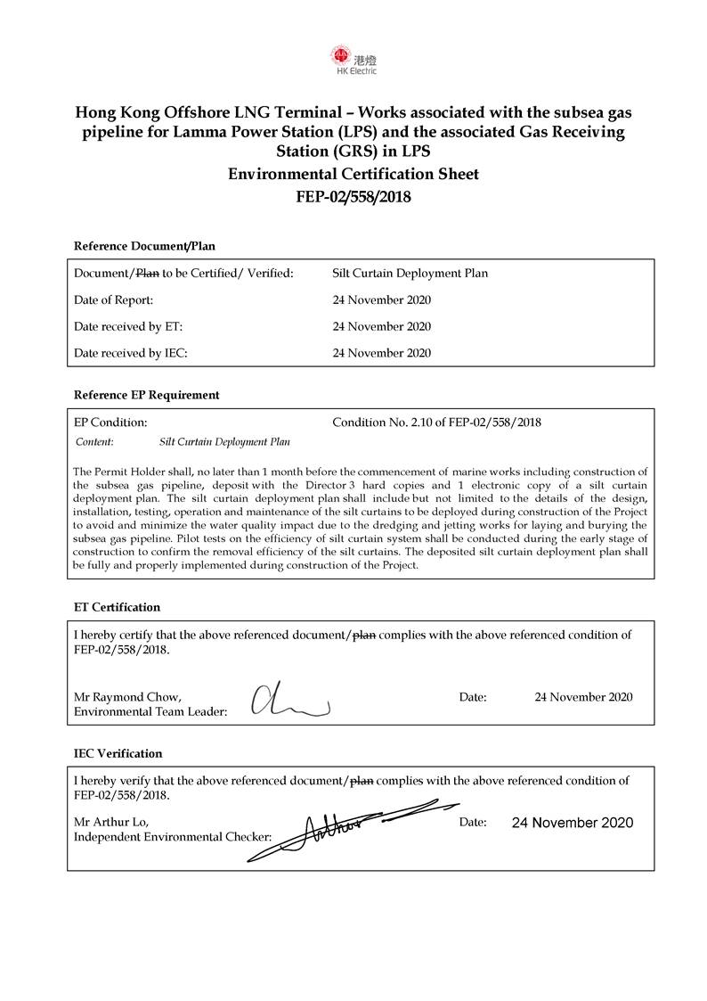
with Condition 2.10 of the Further Environmental Permit FEP-02/558/2018.
|
FEP No. FEP-02/558/2018, Condition 2.10:
“The Permit Holder shall, no
later than 1 month before the commencement of marine works
including construction of the subsea gas pipeline, deposit with the
Director 3 hard copies and 1 electronic copy of a silt curtain
deployment plan. The silt curtain deployment plan shall
include but not limited to the details of the design,
installation, testing, operation and maintenance of the silt
curtains to be deployed during construction of the Project to avoid and
minimize the water quality impact due to the dredging and jetting works for
laying and burying the subsea gas pipeline. Pilot tests on the efficiency
of silt curtain system shall be conducted during the early stage of
construction to confirm the removal efficiency of the silt curtains. The
deposited silt curtain deployment plan shall be fully and properly
implemented during construction of the Project.”
|
The key objective of this Silt Curtain Deployment Plan is to include the details of the design, installation, testing,
operation and maintenance of the silt curtains to be deployed during
construction of the Project to avoid and minimize the water quality impact due
to the dredging and jetting works for laying and burying the subsea gas
pipeline. Based on the latest design,
the pre-installed pipeline at KP 17.4 will be used for the LPS Pipeline tie-in
and cofferdam construction works are not required for the LPS Pipeline shore
approach. Therefore, this Silt Curtain Deployment Plan focuses on
the silt curtains to be deployed for the dredging and jetting works for the
Project.
The Silt
Curtain Deployment Plan will be reviewed and updated as appropriate, throughout
the course of the construction works to confirm that it remains current with
the latest detailed information and works practice.
As stipulated in
Condition 3.3 of FEP-02/558/2018, silt curtains shall be properly installed,
tested, operated and maintained during construction of the subsea gas pipeline
in accordance with the Silt Curtain Deployment Plan deposited under Condition
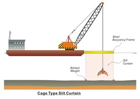
2.10 of FEP-02/558/2018. Cage-type silt
curtain shall be installed enclosing the grab dredger and jetting machine
during construction of the subsea gas pipeline.
No silt curtain installation shall encroach onto the existing marine
parks and the proposed South Lantau Marine Park.
Two types of silt
curtains will be deployed for the dredging and jetting works of the Project:
§ Cage-type silt
curtain will be installed enclosing the grab dredger / jetting machine during dredging
/ jetting works for the construction of the subsea gas pipeline; and
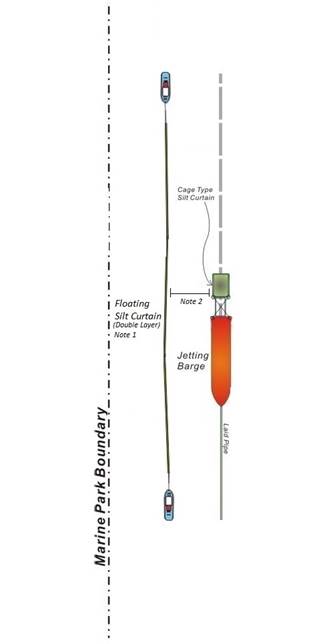
§ Floating
double layer silt curtain will be deployed prior to the jetting works at KP0.1 –
KP5.0 in order to minimize potential water quality impacts of the proposed
South Lantau Marine Park. Specific
location of the pipeline construction works requiring the deployment of
floating double layer silt curtains is illustrated in Figure 1.2.
The floating double layer silt curtain will be deployed outside the
eastern boundary of the proposed South Lantau Marine Park.
2.1
Cage-type Silt Curtain
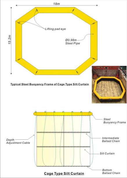
Cage-type silt curtain will be installed for
dredging and jetting activities for the pipeline construction works. A cage-type silt curtain consists of a layer
of geotextile tied on a steel pipe surface buoyancy frame with pipe diameter of
~1,000 mm. The geotextile will be
secured from water surface to seabed level by steel chain ballast. Sufficient length of the geotextile will be
provided such that the silt curtain can be extended from the water surface to
the seabed level during high tide condition.
Silt curtain with various curtain depth and curtain strength of around 110
kN/m will be deployed. The bottom part
of the silt curtain will be kept away from the seabed by a distance of ~0.3m in
order to avoid disturbing the seabed. The
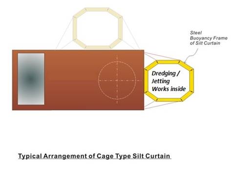
indicative design of cage-type silt curtain is illustrated in Figure 2.1 and the typical arrangement of cage-type
silt curtain installed on a work barge is illustrated in Figure 2.2.
Figure 2.1 Cage-type Silt Curtain Indicative Design
Remark:
The shape and dimension of the cage-type silt curtain are indicative and
subject to modification depending on site conditions.
Figure 2.2 Typical Arrangement of Cage-type Silt
Curtain
2.2
Floating Silt Curtain
Floating silt curtain will be deployed along the
eastern boundary of the proposed South Lantau Marine Park during the jetting
works at Double
Berth Jetty to South of Shek Kwu Chau (KP0.1-5.0). No silt curtain
installation will encroach onto the existing and proposed marine parks.
The floating silt curtain consists of two
layers of geotextile mounted onto polystyrene foam float with diameter of ~500 mm
with polyethylene protective hard shell cover.
The geotextile will be extended slightly above the seabed level and
secured by steel chain ballast or equivalent (e.g. concrete sinkers) to avoid
the bottom part of the silt curtain from touching the seabed and causing
unnecessary disturbance of seabed sediment. The bottom part of the silt curtain will be
kept away from the seabed by a distance of ~0.3m in order to avoid disturbing
the seabed.
The length of the silt curtain deployed at the
active jetting location will be determined considering the findings of the EIA
Report, the potential impact to existing marine traffic for review by the
Marine Department and the performance of the pilot test (see details in Section 4) upon agreement with the
Environmental Team (ET) and the Independent Environmental Checker (IEC). The
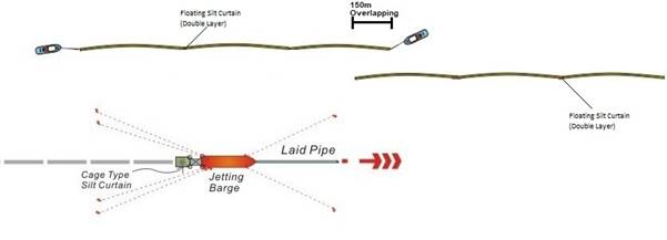
floating silt curtain will be pulled at both ends by tug boats to maintain
tension. Surface structure of the floating silt curtain will be linked to a
towing rope instead of being towed by motor tugs directly for manoeuvring in
order to reduce the tension of the floating silt curtain during towing. Flashlight will be installed on marker buoys
and tug boats for alerting marine operators at night. Should the floating silt curtain be necessary
to be separated into sections, a distance of ~150m overlapping between two
sections of the floating silt curtain will be maintained as far as practicable
to mitigate potential water quality impacts between two floating silt curtain
sections. The floating silt curtain will
be shifted during jetting depending on the location of jetting operation. Should there be any unacceptable water
quality impacts to the water sensitive receivers at the proposed South Lantau
Marine Park from the impact water quality monitoring, the Contractor(s) will
propose remediation measures (e.g. checking of silt curtain integrity,
extension of floating silt curtain) in consultation with the ET and the
IEC.
The indicative arrangement for floating silt
curtain is illustrated in Figure 2.3. The indicative arrangement for floating silt
curtain in sections is illustrated in Figure 2.4. The specification of the proposed geotextile
is shown in Table 2.1. The details
of manufacturer / supplier’s specifications and project references are shown in
Annex D.
Figure 2.3 Indicative Arrangement of Floating Silt
Curtain
Notes:
1)
Preliminary 1000m length, subject to site conditions and trial.
2)
Distance between silt curtain and metal frame will be subject to site condition
and trial.
Figure 2.4 Indicative Arrangement of Double Layer
Silt Curtain in Sections
Table 2.1 Specification of the Proposed Geotextile
|
Technical Data Sheet
|
|
Polymer
|
Density
|
Melting Point
|
Construction
|
|
100% Polypropylene
|
0.91 kg/dm3
|
165 °C
|
Tapes
|
|
Properties
|
|
Mechanical Properties
|
Standard
|
Performance
|
Tolerance
|
|
Tensile strength - MD
|
EN ISO10319
|
110 kN/m
|
-9.9 kN/m
|
|
Tensile strength - CMD
|
EN ISO10319
|
110 kN/m
|
-9.9 kN/m
|
|
Elongation at maximum load - MD
|
EN ISO10319
|
10 %
|
+/- 2.3 %
|
|
Elongation at maximum load - CMD
|
EN ISO10319
|
8 %
|
+/- 1.8 %
|
|
Static puncture resistance (CBR)
|
EN ISO12236
|
12.5 kN
|
-2.5 kN
|
|
Dynamic perforation resistance (cone drop)
|
EN ISO13433
|
10 mm
|
+2.0 mm
|
|
Tensile strength at 2% elongation - MD
|
EN ISO10319
|
15 kN/m
|
|
|
Tensile strength at 2% elongation - CMD
|
EN ISO10319
|
25 kN/m
|
|
|
Tensile strength at 5% elongation - MD
|
EN ISO10319
|
45 kN/m
|
|
|
Tensile strength at 5% elongation - CMD
|
EN ISO10319
|
60 kN/m
|
|
|
Hydraulic Properties
|
Standard
|
Performance
|
Tolerance
|
|
Water permeability normal to the plane
(Vlh50)
|
EN ISO11058
|
25 l/m2s
|
-8 l/m2s
|
|
Characteristic Opening Size (O90)
|
EN ISO12956
|
230 µm
|
+/- 69.0 µm
|
|
Physical Properties
|
Standard
|
Performance
|
Tolerance
|
|
Weight
|
EN ISO9864
|
464 g/m2
|
+/- 46.4 g/m2
|
|
Length (+/- 1%) x width (+/- 1%)
|
-
|
100 x 5.25 m
|
-
|
|
Truck Load Volume (+/- 10%)
|
-
|
30,450 m2
|
-
|
|
Roll diameter (+/- 10%)
|
-
|
45 cm
|
-
|
|
Durability
|
Standard
|
Performance
|
|
Predicted minimal durability in years in
natural soils with 4 <pH < 9 and soil temperature <25°C
|
EN ISO13438 - A2
|
25 years
|
|
Maximum allowed time between installation and
covering of the geosynthetic
|
EN 12224
|
2 weeks
|
|
|
|
|
|
Cage-type silt curtain will be fixed and hung underneath the frame by
nylon rope on deck of crane barge after the completion of fabrication of steel
buoyancy frame. The skirt of cage-type
silt curtain will be coiled by tightening rope for easy deployment.
The entire steel buoyancy frame with cage-type silt curtain will be
lifted and erected to the grab dredger or jetting machine when the rigging
structure or mounting brace is ready.
The coiling ropes will be cut at the steel buoyancy frame and the
curtain skirt will be released to the seabed for enclosure.
Cable ropes pre-installed at the bottom of the cage-type silt curtain
will be lifted up and tightened at the steel buoyancy frame to adjust the depth
of curtain skirt on site from time to time.
Floating silt curtain will be
delivered to the location for fixing by flat top/crane barge. All vertical joints of each span of the
floating silt curtain will be connected and tied up and coiled with ropes in a
tube-form pattern by workers working on deck of the barge.
Steel chain ballast or
equivalent (e.g. concrete sinkers) will be deployed at the designated positions
along the route by crane barge equipped with real-time global positioning
system when the position of floating silt curtain is confirmed.
One of the ends of the towing
rope will be picked up and the floating silt curtain will be lowered down
slowly into the water by the main towage front tug when the floating silt
curtain is available for deployment.
Coiling rope will be cut by small work boat,
and the curtain skirt and ballast chain will be released into the water after
the other end of towing rope is secured at the back tug and all tugs are in
position.
The works activities
(i.e. dredging / jetting works) requiring deployment of silt curtains in the
corresponding locations are shown in Table 3.1.
Table 3.1 Locations of Deployment of Silt Curtain
|
Work Location
|
Cage-type Silt Curtain
|
Floating Silt Curtain
|
|
LPS Pipeline Riser
(LPS KP0.0-0.1)
|
Yes
|
No
|
|
Double Berth Jetty to South of Shek Kwu Chau
(LPS KP0.1-5.0)
|
Yes
|
Yes (at
Eastern Boundary of the Proposed South Lantau MP)
|
|
South of Shek Kwu Chau to West Lamma Channel
(LPS KP5.0-14.5)
|
Yes
|
No
|
|
West Lamma Channel
(LPS KP14.5-17.4)
|
Yes
|
No
|
As stated in Condition 2.10 of FEP-02/558/2018
and Section 5.3.2 of the Updated EM&A Manual of the Hong Kong Offshore LNG
Terminal Project, pilot tests on
the efficiency of silt curtain system shall be conducted during the early stage
of construction to confirm the removal efficiency of the silt curtains. The pilot test will be conducted by measuring
turbidity and suspended solids (SS) at selected stations within and outside
silt curtains to be discussed below.
The pilot test on silt curtain systems will
include the following tests:
§ Silt curtain at grab dredger (testing of silt
removal efficiency of 75% or higher);
§ Silt curtain at jetting machine (testing of
silt removal efficiency of 85% or higher); and
§ Double layer of silt curtains at sensitive
receivers (testing of silt removal efficiency of 80% or higher).
The results of the pilot tests
to be conducted during the early
stage of construction will be applicable to dredging / jetting works for
the Hong Kong Offshore LNG Terminal Project, i.e. the subsea gas pipeline for
BPPS under FEP-03/558/2018 and the subsea gas pipeline for LPS under
FEP-02/558/2018.
During the pilot test, dredging/ jetting works
shall be actively undertaken within the works areas with the silt curtains deployed,
and shall be operated at or close to the maximum productivity. The surrounding environment will be controlled
as far as practicable such that there would be no other major construction
activities with potential of generating suspended solids being operated
concurrently.
The pilot test covers two
different types of silt curtains proposed, the cage-type silt curtain and the
floating silt curtain.
4.2.1.1
Cage-type
Silt Curtain during Dredging and Jetting
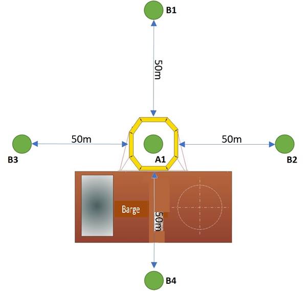
There will be five monitoring
stations of which one will be inside the cage while the rest will be outside
the silt curtain in four directions. The
indicative monitoring locations for cage-type silt curtain during dredging and
jetting are shown in Table 4.1 and Figure 4.1.
Table 4.1 Indicative Monitoring Locations for Cage-type
Silt Curtain during Dredging and Jetting
|
Monitoring Station
|
Location
|
Description
|
|
A1
|
Within silt curtain
|
One monitoring station will be located inside the cage
|
|
B1
|
Outside silt curtain
|
Four monitoring stations will be located at four sides of
silt curtain and within ~50 m from the silt curtain boundary
|
|
B2
|
|
B3
|
|
B4
|
Remark: Each
applicable station will be sampled and measurements/ water samples will be
taken at three depths, 1m below the sea surface, mid-depth and 1m above the
seabed. For stations that are less than 3m in depth, only the mid-depth
sample shall be taken. For stations that are less than 6m in depth, only
the sea surface and bottom samples shall be taken. For in-situ measurements, duplicate
readings shall be made at each water depth at each station. Duplicate
water samples shall be collected at each water depth at each station.
Figure 4.1 Indicative Monitoring Locations for
Cage-type Silt Curtain during Dredging and Jetting
Note: The actual monitoring locations will be determined on
site considering the locations of the cage-type silt curtain, anchor wires of
the barges and nearby marine traffic conditions.
4.2.1.2
Floating
Silt Curtain
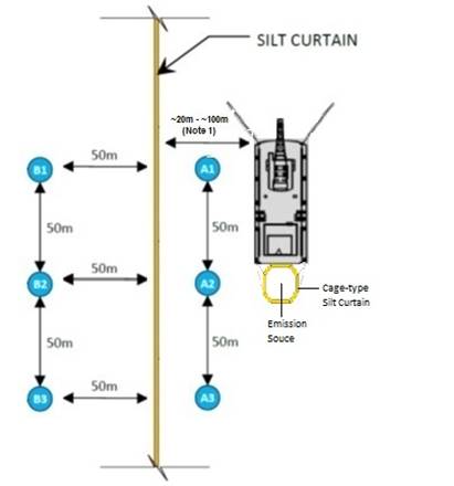
There will be six monitoring
stations of which three will be near the marine works area while the rest will
be at the other side of the silt curtain.
As the floating silt curtain will be placed at water sensitive
receivers, the distance between the emission source and the silt curtain for
the pilot test is expected to be ranged from ~20 m to ~100 m depending on the
location where the pilot test will be conducted in the vicinity of water
sensitive receivers (e.g. the proposed South Lantau Marine Park). The indicative monitoring locations for
floating silt curtain are shown in Table 4.2 and Figure 4.2.
Table 4.2 Indicative Monitoring Locations for
Floating Silt Curtain
|
Monitoring Station
|
Location
|
Description
|
|
A1
|
Near marine works area
|
Three monitoring stations will be ~50 m apart from each
other and situated between marine works area and the silt curtain boundary
|
|
A2
|
|
A3
|
|
B1
|
The other side of silt curtain
|
Three monitoring stations will be ~50 m apart from each
other and situated at ~50 m from the other side of silt curtain boundary
|
|
B2
|
|
B3
|
Remarks:
1) Each applicable station will be sampled and
measurements/ water samples will be taken at three depths, 1m below the sea
surface, mid-depth and 1m above the seabed. For stations that are less
than 3m in depth, only the mid-depth sample shall be taken. For stations
that are less than 6m in depth, only the sea surface and bottom samples shall
be taken. For in-situ measurements,
duplicate readings shall be made at each water depth at each station.
Duplicate water samples shall be collected at each water depth at each station.
2) Measurements/ water samples will be taken at
representative tidal condition during which the direction of water currents will
be from marine works area towards silt curtain.
Figure 4.2 Indicative Monitoring Locations for Floating
Silt Curtain
Note 1: The distance will depend on the location
where the pilot test will be conducted in the vicinity of water sensitive
receivers.
The testing parameters for the
pilot test are shown in Table 4.3. Other relevant data will also be measured and
recorded during the pilot test, including the location of the monitoring
stations, water depth, time, weather conditions, sea conditions, tidal state,
current direction and velocity, special phenomena and dredging / jetting rate
during the pilot test. The monitoring
equipment to be used, sampling / testing protocols, laboratory measurement and
analysis will follow the requirements as stated in the Updated EM&A Manual.
Table 4.3 Testing Parameters and Equipment for
Pilot Test
|
Parameter
|
Unit
|
Abbr.
|
Equipment
|
Reporting Unit
|
|
In-situ measurements
|
|
Turbidity
|
NTU
|
-
|
Instrumental, CTD
|
0.1
|
|
Laboratory measurements
|
|
Suspended solids
|
mg L-1
|
SS
|
APHA 2540E
|
1.0
|
|
|
|
|
|
|
4.2.3 Timing and Duration
The pilot test will be scheduled to be
conducted during the early stage of construction:
§ three rounds within a single monitoring day covering
mid-ebb and mid-flood tides for cage-type silt curtain for dredging works. Each round of monitoring will be conducted
when dredging works are operated at or close to the maximum productivity and the
measurement at each monitoring station between any two rounds will be separated
by at least 1 hour. The monitoring will
be scheduled when relatively high current speed condition is expected on the
day of testing, as far as practicable;
§ three rounds within a single monitoring day
covering mid-ebb and mid-flood tides for cage-type silt curtain for jetting
works. Each round of monitoring will be conducted
when jetting works are operated at or close to the maximum productivity and the
measurement at each monitoring station between any two rounds will be separated
by at least 1 hour. The monitoring will
be scheduled when relatively high current speed condition is expected on the
day of testing, as far as practicable; and
§ three rounds within a single monitoring day for
floating silt curtain. Each round of
monitoring will be conducted when jetting works are operated at or close to the
maximum productivity and the measurement at each monitoring station between any
two rounds will be separated by at least 1 hour. The monitoring will be scheduled when the representative
tide with relatively high current speed condition is expected on the day of
testing, as far as practicable. Measurements/
water samples will be taken at representative tidal condition during which the
direction of water currents will be from marine works area towards silt curtain
for the pilot test for floating silt curtain.
Given the monitoring design of the pilot test
is to measure near-field water quality around the emission source to determine
the silt-retaining effectiveness of the silt curtain system, the proposed pilot
test monitoring frequency (i.e. three rounds within a single monitoring day
when relatively high current speed condition is expected on the day of testing
and during representative tide with relatively high current speed condition
which the direction of water currents will be from marine works area towards
floating silt curtain to represent worst case scenario for the silt curtain
system in terms of the silt-retaining capacity and integrity) is considered
adequate.
During the pilot test, the dredging / jetting
works shall be actively conducted within the works areas at a representative
work rate not exceeding the allowed maximum work rate as stated in the Updated
EM&A Manual. The surrounding
environment should be controlled as far as practicable such that there would be
no other major SS-generating construction activity operating concurrently in
the vicinity that may influence the pilot test results.
Considering that the pilot test will be
conducted during the early stage of construction, the findings of the pilot
test will be reported in the corresponding monthly EM&A report for the
month in which the pilot test would be conducted, and the following information
will be reported:
§ Location plan(s) showing the monitoring
stations for the corresponding silt curtains;
§ Results of in-situ
and laboratory measurement (in summary and full dataset); and
§ Findings from the evaluation of pilot test
results and recommendations for improvements, if any.
Silt curtain efficiency is determined by the difference between the SS
level () near marine
works area and that outside silt curtain.
The following equation is adopted to determine silt curtain efficiency:

where, SS (inside) is determined by averaging the SS levels inside the
marine works area (e.g. the average of A1 to A3 for floating silt curtain); SS
(outside) is determined by averaging the SS levels at monitoring stations
outside the silt curtains (i.e., the average of B1 to B3 for floating silt
curtain; the average of B1 to B4 for cage-type silt curtain).
Should the efficiency of the
silt curtain system to be adopted did not satisfy the requirements in the approved
EIA Report, the Contractor shall propose further measures / improvements to the
silt curtain system for consideration by HK Electric, the ET and the IEC. However, regardless of the measured efficiency
of the silt curtain system, the Event and Action Plan established in the
Updated EM&A Manual shall only be based on the monitoring results of the
construction phase water quality monitoring at the impact monitoring stations.
The Contractor will check the
condition of the silt curtain (both cage type and floating silt curtain) before
commencement of works every day. Refuse around the silt curtains will be
collected regularly and as needed on a daily basis so that water behind the
silt curtains will be kept free from floating debris. Sufficient spare geotextile will be kept on
site for replacing damaged silt curtains.
The spare geotextile shall be kept appropriately to avoid direct contact
with water and sunlight.
Underwater silt curtain inspection
will be carried out after adverse weather (e.g. Typhoon Signal No. 3 or above). Underwater silt curtain inspection will also be
conducted after installation / re-installation / relocation of silt curtains /
suspected sediment release due to ineffectiveness of silt curtain (e.g. from
the impact water quality monitoring results to be conducted by the ET,
observations by the Contractor(s), HK Electric, ET or IEC). Underwater silt curtain inspections shall
cover at least a 10m length of silt curtain or one whole silt curtain panel
(whichever is greater) at each location, and at intervals of at least every
200m along the length of silt curtains deployed. The underwater inspections shall check that
the silt curtain fabric is intact, the silt curtain depths and ballast weight
(for cage-type silt curtain) and steel chain ballast or equivalent (e.g. concrete
sinker) (for floating silt curtain) positions are correct, and there is no damage
/ breakage in ballast weights/ steel chain ballast or equivalent and load
lines. Photographic records shall be
taken during each underwater inspection. All identified defects / damage shall be
photographed and the position recorded on GPS to enable the affected areas to
be subsequently located for in-situ repair where appropriate. An inspection checklist will be prepared and
filled in by the Contractor, and endorsed by HK Electric. All checklists will be kept on site for
record purpose.
In the event of silt curtain
being damaged and/or requiring repairing works at the corresponding works
locations, the related dredging / jetting works will be suspended immediately
until the rectification works for the silt curtain is completed subject to the
satisfaction by HK Electric.
Samples of Silt Curtain Daily
Inspection Checklist and Underwater Inspection Checklist are shown in Annex A and Annex
B, respectively.